Aurora Networks® (ANS) and RUCKUS® Networks are now Vistance Networks
Cat 6A: the Fact File
Cat 6A: two decades old and still growing
Although Cat 6A first appeared in 2004 in the form of CommScope’s SYSTIMAX® GigaSPEED® X10D, it would not be formally published as a standard until 2009. By then, however, it was known across the industry as the cabling category of the future that would enable the next wave of high-bandwidth copper connectivity. This was why cabling manufacturers quickly tried to replicate it and standards bodies were compelled to publish an agreed standard.
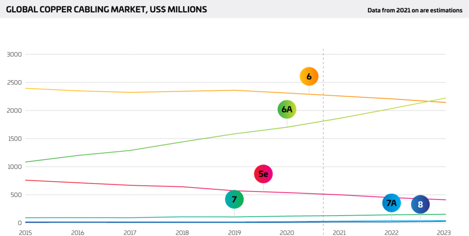
Looking back, we see that it has enabled the development and deployment of many bandwidth-hungry applications that today’s enterprises cannot do without. And it is not finished yet – it remains the recommended infrastructurei for modern new-builds and promises to remain relevant for many years to come. Proof of its success can be seen in the sales volume that continues to grow, almost two decades after the initial draft of the standard.
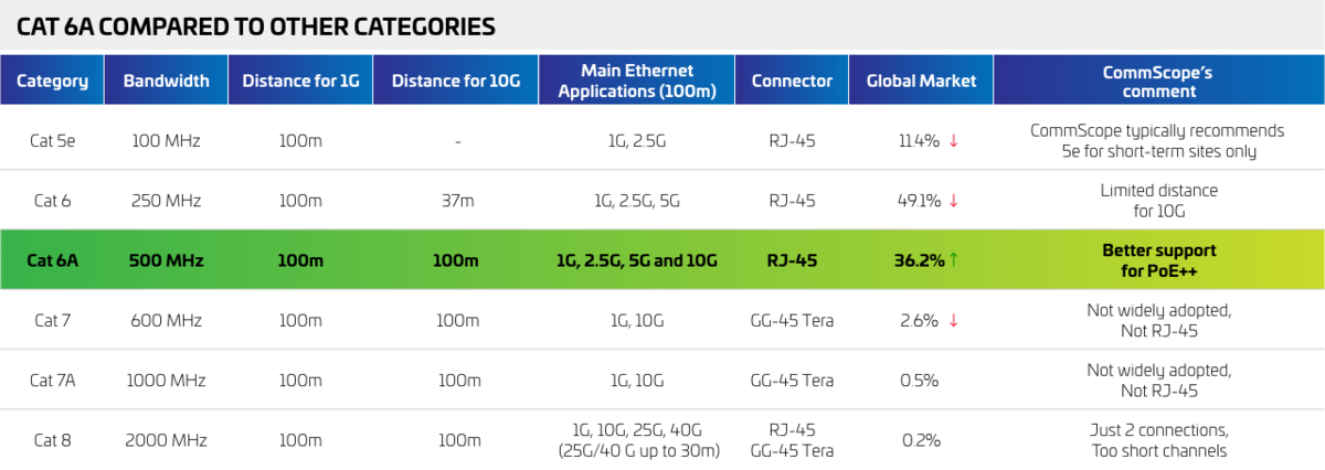
In this article, we will also explore why Cat 6A took over previous categories (Cat 5, Cat 5e, Cat 6) and why it’s a better option than - theoretically superior - copper cabling types such as Cat 7, Cat 7A and even Cat 8.

Technology overview of SYSTIMAX cabling
Would you like to read offline?
Download a PDF version of this article to read again later.
Stay informed!
Subscribe to The Enterprise Source and get updates when new articles are posted.
We have always known that enterprise networks need to evolve rapidly to support the growing demand for bandwidth-hungry applications. End users take advantage of these applications to exchange more information in novel ways, and enterprise organizations generally find ways of consuming as much bandwidth as offered up to them very quickly.
With this in mind, the industry realized back in 2004 that it needed to escape the confines of 1000Mbps Cat5 and Cat6 cabling categories. The next step in the evolution of networking was obvious: the world needed 10 Gigabit Ethernet and the IEEE 802.3an 10GBASE-T Task Force was entrusted with the task of developing the standard.
Due to the expected complexity of electronics to support 10GBASE-T, an early objective to support Category 5e had been dropped, and the exact maximum distance over minimally compliant Category 6 cabling was still uncertain. The final mandatory objective for the IEEE 802.3an project was “at least 55m to 100m” over Category 6 or better cabling. Many expected that, as the clever chip designers further dive into this project, novel techniques would be developed which would increase the minimum guaranteed distance over generic Category 6 cabling.
In simple terms, there were three ways of transmitting higher bit rates over cabling. One was to improve the cabling performance, the second was to improve the technology in the electronics, and the third required a mixture of both. The latter was true for 10 Gigabit over copper. Transmitting 2.5 Gb/s on each of the four pairs was no easy task: it required multi-level coding that transmitted multiple bits per hertz, and channel bandwidth greater than that specified in the existing Category 6 standards. Sophisticated Digital Signal Processing (DSP) techniques were also required to reduce the effects of within-channel impairments such as return loss and crosstalk (NEXT and FEXT). However, there was also one parameter that could not be compensated for in the electronics – Alien Crosstalk (the noise from adjacent cabling channels).
The IEEE 802.3an Task Force began actively exploring these issues, and interfacing with the ISO and TIA cabling standards to converge on its cabling channel requirements. The result of these developments led the IEEE 802.3an Task Force to adopt minimum cabling channel specifications for 10GBASE-T, and to recognize officially what became known as Model 1 Alien NEXT and Insertion Loss as the Model applicable to “Augmented” Category 6 or “new” Class E (Class EA). In addition, the Task Force agreed to set the maximum required channel frequency at 500 MHz.
Thus, with the publication of the draft standard in October 2004, Cat 6A was born. It was ahead of its time, and was deliberately designed to provide maximum ‘future-proofing’. One key aspect of its suitability as the infrastructure for a new generation of applications and uses was that it made PoE (Power over Ethernet) a possibility. Not only could Cat 6A support 10Gbps speeds, but it also greatly expands the ability for device manufacturers to deliver higher power and bandwidth anywhere, without distance limitations –other than the maximum channel length of 100 m–, because devices can be located anywhere within reach of a PoE switch and not an AC outlet.
Almost two decades later, Cat 6A is the dominant copper twisted pair category – and is still recommended for all new-build applicationsii. Read on to find out how it works, how to implement it, and how it is a networking bedrock upon which future multi-gigabit applications and services will be built.
What applications are ideally suited to Cat 6A?
Large enterprises are faced with a growing need to accommodate ever more sophisticated applications. Any structured cabling implementation should be independent of these considerations, providing a stable, high-speed infrastructure that is technology-agnostic.
Horizontal standard office applications: Most phones and laptops do not yet require the 10 Gbps bandwidth, but using Cat 6A as the default cabling infrastructure provides a future-proof infrastructure. It may be years until such everyday applications require such bandwidth, but it will be there when needed.
IoT: As IoT devices begin to proliferate, Cat 6A provides both the bandwidth and, potentially, the power requirements. Find out more about how IoT is changing the fabric of business and everyday life.
PoE/lighting: As mentioned, IoT devices such as sensors or cameras have a ready source of power across Cat 6A, and it is also increasingly used to power lighting systems, made possible by the development of low-voltage LEDs. Cat 6 cabling does enable PoE, but may be prone to heat problemsiii.
Wi-Fi 6/6E: Cat 6A is necessary to deliver the multi-gigabit backhaul required by the next-generation of Wi-Fi. Find out how Wi-Fi 6 and 6e provides the performance and capacity needed by mobile users, IoT devices, and latency-sensitive applications.
In-Building Cellular: Multi-gigabit backhaul is also required for DAS installations, necessitated by increased reliance on cellular networks alongside Wi-Fi.
Storage Area Networks (SAN)/ Network Attached Storage (NAS): 10 Gigabit Ethernet enables cost-effective, high-speed infrastructure for both network-attached storage (NAS) and storage area networks (SAN). 10 Gigabit Ethernet can offer equivalent or superior data carrying capacity at latencies similar to many other storage networking technologies, including Fiber Channel, ATM OC-3, OC-12 and OC-192, and InfiniBand. The development of 10 Gigabit over copper will offer a very cost-effective solution for connection under 100 meters compared to these traditional fiber based technologies.
High-Performance Computing: A number of industry sectors utilize high-performance computing platforms to support highly bandwidth-intensive applications such as streaming video, medical imaging, centralized applications, high-end graphics, visualization technologies, and data clustering.
Multi-Site Collaboration: Collaboration tools are emerging that enable conference participants to write or draw on a blank slide, to connect to a Web site, and engage in private communication with the conferencing host or any other participants. To ensure their effectiveness, these collaborative tools will increasingly require more bandwidth, and 10 Gigabit Ethernet connections will be the primary link for enabling multi-site collaboration within an enterprise.
Streaming Media, AV systems and Digital Signage: Streaming media enhances a company’s internal and external communications. It can play a role in hosting meetings, holding press conferences, demonstrating new products, supporting marketing/advertising activities, training employees, providing user support as well as the fun stuff too, like HDTV, video on-demand or extreme Internet gaming. Since data being transmitted for streaming media requires an uninterrupted path between source and user, bandwidth will be the key enabler and accelerator to streaming media adoption.
Grid Computing: Grid computing makes "spare" desktop CPU horsepower available across the network to large jobs that require it. There are many scientific applications that need the computing power of arrays, but up to now the cost of a supercomputer or a massively parallel array was prohibitive. Grid computing is a technique that effectively provides the horsepower "across the network" to support these kinds of applications. Grid computing is highly dependent upon very fast interconnections among all of the participating computing platforms. Today, grid computing is being used to amass spare compute cycles in datacenters to power complex modeling and simulations in applications such as pharmaceutical research, financial portfolio risk analysis, electronic design automation and other computer-intensive applications. For grids to be the basis of a corporate infrastructure, more types of applications that can take advantage of the grid will be developed but in the meantime, grid technologies can and are being used to facilitate resource sharing, utilization and collaboration for a growing number of applications and industries.
10. Category 6A is recommended for new installations in healthcare facilities.
Published in 2010, TIA-1179 recommends Category 6A for all new installations in healthcare facilities and was the first standard to recommend Category 6A for new installations outside of the data center.
9. Category 6A is recommended for new installations in educational facilities.
Published in 2014, TIA-4966 recommends Category 6A for new education facilities based on the need for high-performance infrastructure required for wired and wireless connectivity.
8. Category 6A supports 10GBASE-T to 100 meters.
Category 6A’s support of 10GBASE-T to 100 meters ensures it can support the fastest Ethernet applications over twisted pair media on the market to the full channel length specified in the standards (TIA-568 and ISO/IEC 11801 to quote a few). This comes at a time when high-performance workstations are beginning to demand 10 gigabit performance as well.
7. 10GBASE-T provides improved price performance and lower power consumption.
Dramatic improvements to 10GBASE-T over the last few years result in significantly lower overall price and power efficiency per gigabit than 1000BASE-T. It looks like the old industry saying, “Today’s server is tomorrow’s desktop,” may be applicable to 10GBASE-T.
6. Category 6A supports the familiar and backwards compatible RJ45 user interface.
Category 6A supports the tried and true, familiar, and backwards-compatible RJ45 interface. The RJ45 demonstrated the power of standardization, has enabled the global growth of Ethernet as we know it, and has become a universal interface for a broad range of applications.
5. Category 6A supports new in-building wireless systems that rely on 10G technology.
Contrary to popular belief, wireless needs wires. New in-building wireless systems relying on 10GBASE-T LAN technology and remote powering over Category 6A that support multi-operator and multi-technology coverage and capacity solutions in buildings are already in the market.
4. Category 6A supports Wi-Fi technologies already exceeding 1 Gbps.
Today’s 802.11ax (aka Wi-Fi 6) access points can have a maximum speed of 6.77 Gbps, which would require a 10GBASE-T connection to operate at the highest data rate they are capable of running. TSB-162-A, Telecommunications Cabling Guidelines for Wireless Access Points, also recommends running at least Category 6A or higher cabling to all wireless access points.
3. Category 6A is globally available in unshielded and shielded versions.
The debate about the virtues of unshielded and shielded solutions will continue. Category 6A (and CommScope) supports both, while customers continue to speak with their wallets in favor of the more familiar, and easier to install, unshielded solutions.
2. Category 6A provides superior performance for Power over Ethernet (PoE) applications.
At a time when the PoE standards are updated to double the power delivered to devices utilizing all four pairs in the cable, Category 6A offers enhanced thermal dissipation performance over its Category 5e and Category 6 predecessors. Read more in this white paper on Category 6A advantages for PoE.
1. Category 6A offers simple and cost-effective provisioning to support current and emerging applications.
Category 6A offers the most cost-effective and simple provisioning to prepare today’s buildings for current and future applications. With 10 gigabit applications starting to emerge, the time is right to consider provisioning the building with the right copper cabling infrastructure based on Category 6A twisted pair connectivity.
Lowest cost per transmitted gigabit!

10 reasons to choose CAT6A

10 reasons to choose CAT6A
Initial concerns
When the first wave of Category 6A cable came out, some commented on the fact that it was significantly larger and heavier than the average Cat 6 cable. However, over the last decade or so, improvements have been made to address such concerns, making it slimmer and lighter. There were other initial differences too, such as only being available on reels instead of convenient pull-boxes, but most suppliers have addressed this (eg CommScope’s use of WeTote boxes).
Lack of specification?
In addition, given the relative complexity and sophistication of Cat 6A, it is important to test, yet many vendors failed to provide a guaranteed performance or specification document. The result was that many Cat 6A deployments would go live without adequate testing. Full specifications of SYSTIMAX GigaSPEED X10D, however, can be found in this guide.
Worth the weight
While Cat 6A remains a more substantial cable than its predecessor, its ability to carry 10 Gbps over longer distances and reduce crosstalk more than outweighs such considerations. The equivalent of 10x Cat 6 cables that would be required to match the performance of Cat 6A would be unmanageable!
Until the advent of the Category 5 systems and cabling standards, LAN performance was limited primarily by the building cabling and the ability of the LAN equipment to properly decode the signals that were distorted by the cable. The improvement in performance seen with Category 5 at the time alleviated this issue. However, as LAN speeds continued to increase, a similar issue emerged as equipment designers tackled the requirement to support gigabit type speeds over the infrastructure, hence the move to Category 5e and 6 specifications. As LAN speeds increased to 10 Gbps and cable and connector technology inevitably improved, the LAN designer had to account for the impact of all channel components, and their installation, have on performance.
The GigaSPEED X10D solution was specifically engineered with enhanced cable and connector performance designed to support the emerging 10 Gbps Ethernet requirements. Using patented technology and the scientific capabilities of SYSTIMAX Labs, the GigaSPEED X10D solution exhibits far superior channel performance for legacy solutions, and innovative engineering techniques to meet the specific demands 10 Gbps brings to the physical layer.
The cabling architecture used to provide a communication channel is based on a 4-connector channel. This portion of the cabling system referred to as the Horizontal sub-system, (between the floor distributor and the work area) is the area where most debate over LAN and cabling performance occurs.
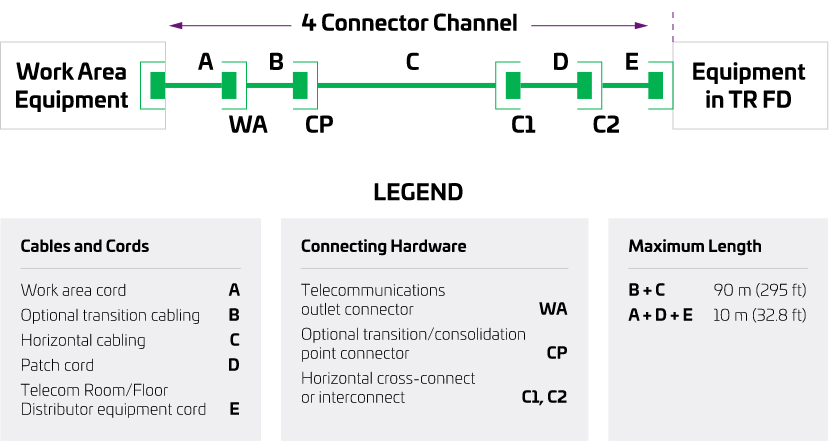
The data carrying capacity of a structured cabling system is affected by a number of impairments introduced into the channel by the system components and their surrounding environment. Several of the impairments that negatively impact the throughput of a structured cabling system are listed below.
- External Noise
- Delay and Delay Skew
- Insertion Loss/Attenuation
- Impedance Mismatch/Return Loss
- Crosstalk
These potential impairments can cause bit errors, which can reduce the overall throughput of a structured cabling system channel. Bit-Error-Rate (BER) is the ratio of the number of incorrectly received bits to the number of bits transmitted. The need to minimize bit errors in order to maximize throughput, is critical as high-speed, bandwidth intensive applications emerge. In data applications, higher BER results in slower network performance due to signal retransmissions. In video applications, higher BER results in choppy displays, missed frames, and the creation of white speckles (snow). In each application area, higher BER results in unsatisfactory performance.
The key cabling parameters are Impedance, Channel Return Loss, Insertion loss and Crosstalk, and an understanding of these is essential in assessing this cabling system’s full potential.
Noise is coupled into the channel via external electrical and magnetic fields located in the vicinity of the channel. A non-direct discharge of Electro Static Discharge (ESD) or an Electrical Fast Transient (EFT) event is an example of an external noise source. With the GigaSPEED X10D cabling system, this is overcome by the products having excellent balance
Balance is the degree to which the signal on one wire of a pair is equal in amplitude, but opposite in phase on the other wire of that same pair. Each signal is measured relative to earth ground. Assuming that the signal is applied in a perfectly balanced manner, the average voltage is zero. However, the balance can be disturbed. Main causes for this balance disruption are the connectors in the link.
When the channel is not well balanced (for example, the shielding of cables degrades balance), there is a voltage present between the pairs that will be added to the transmitted signal as common mode noise, thus increasing the occurrence of bit errors. The system will depend then on the Common Mode Rejection (CMR) of the receiver to get rid of any effects. Furthermore, unbalance increases emissions and degrades immunity.
In LAN environments, the use of balanced transmission with well balanced electronics and cables eliminates the need for shielding the pairs as a measure against external interference and radiated emission, without the extra concerns of earthing and bonding. Since grounding and earthing requirements differ from one country to another, the only truly ‘portable’ and ‘open’ cabling system is the UTP cabling system.
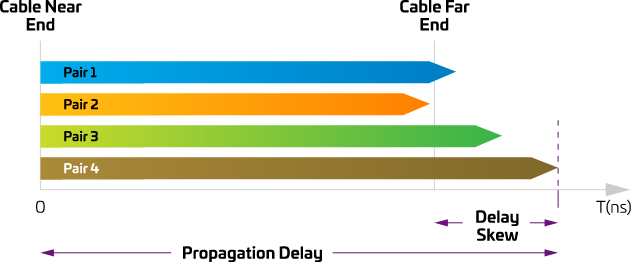
A signal travelling from end to end of a cabling channel is delayed in time by an amount equal to the length of cable divided by the velocity of propagation for that transmission medium. This delay is called Propagation Delay. For practical cables, the velocity of propagation depends on the properties of dielectric materials surrounding the conductors. The cable propagation delay is characterized by the worst case pair.
Delay Skew is the difference in propagation delay between any two pairs within the same cable sheath. This parameter is length dependent and it is possible for a shorter length to pass when it fails at 100 meters. Variations in twist rates, coupled with the dielectric composition of the pairs determine skew, which is expressed in seconds. Minimizing delay skew is critical for applications that require signals to be transmitted over multiple twisted-pairs and arrive at the receiver end of a channel at the same time.
SYSTIMAX GigaSPEED X10D channels have excellent margin for propagation delay and delay skew.
Insertion loss, also known as attenuation, is the loss or diminishing of a signal when it passes through a transmission medium. Loss occurs in any type of transmission medium. The effect of insertion loss is important because this primarily determines the maximum distance that two devices can be separated.
Insertion loss in copper wire is caused by two factors:
- Copper loss, which is unavoidable and similar for all 100 Ohm twisted pairs. This cannot increase significantly because of the limitations on size of insulated wire to be inserted into a RJ45 connector. Hence dramatic increases in attenuation would only be achievable with adoption of a new connector - not wanted by most users.
- Dielectric loss, or dissipation, due to the insulation and jacketing materials used on the conductors and the cable. Minimizing the dissipation loss of the insulating and jacketing materials is important to minimize the cable’s attenuation. The dissipation factor is a relative measurement of a material’s loss.
Insertion loss is usually expressed in dB per unit length (e.g., dB/1,000 feet) and is a measure of how much a signal is weakened or reduced in amplitude as it travels down a cable.
Insertion loss is a key parameter in deciding the available bandwidth used for 10GBaseT.
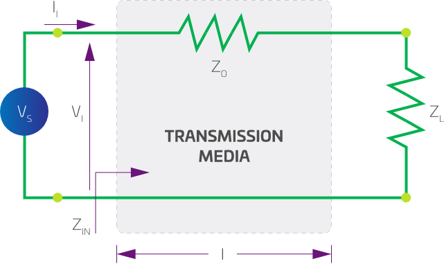
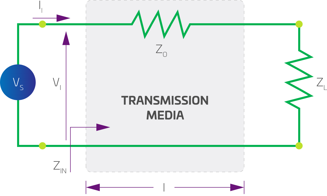
Characteristic Impedance corresponds to the input impedance of a uniform transmission line of infinite length:
It also corresponds to the input impedance of a transmission line of finite length that is terminated in its own characteristic impedance. It is a function of cable construction and the frequency of the applied signal, and is unrelated to length. At very high frequencies, the characteristic impedance tends to a fixed value that is resistive. For example, twisted-pair telephone cables have an impedance of 100 ohms above 1MHz.
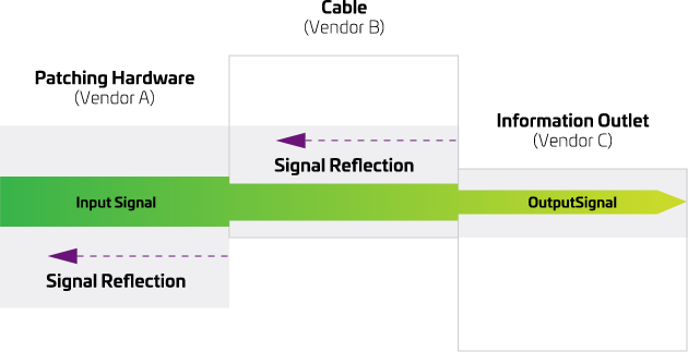
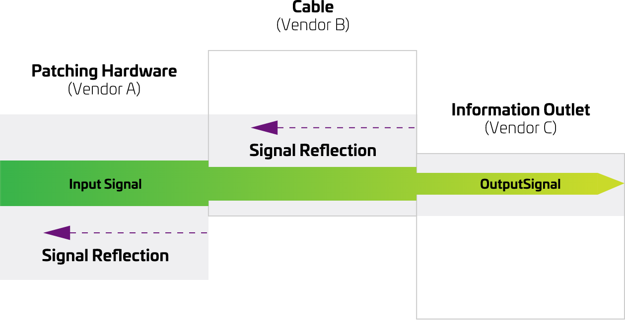
Maximum power is transferred from the source to the load when the load impedance ZL is equal to the transmission line characteristic impedance ZO. Expressed differently, all the energy is transmitted and none of the energy is reflected back at the cable termination. When the terminating or load impedance is different than the characteristic impedance, the signal traveling to the cable is partially reflected at the cable/load junction. The power of the reflected signal is called the Return Loss (R) in dB.
When the geometry of the cable varies along the length, so does its impedance. This fluctuation in impedance also causes reflections.
The Channel Return Loss (RL) is a measure of the consistency of the impedance down the length of not just the cable, but also the connections and the patch cables. The parameters that affect channel uniformity include the average separation distance between the two conductors of a pair, the twist uniformity of the pair, and cross-sectional uniformity of the insulated cores themselves. These parameters are very much measures of the quality of manufacturing of the cables, connectors and patch cords. Even small variations in these parameters will significantly degrade RL performance.
The reason why RL is of concern is that the variation in impedance down the channel causes a form of noise at the receiver. It is therefore important to control the allowable non-uniformity’s to ensure that their effect is small compared to other sources of noise, such as crosstalk. Return loss is important for bi-directional transmission schemes (dual duplex) where one pair is used to transmit and receive at the same time. Note that a transmission scheme can be full duplex without being dual duplex (e.g. transmit on one pair, receive on another pair).
Minimizing impedance mismatch within a channel becomes important when attempting to support an application such as 1000BASE-TX or 10GBASE-T that employ a hybrid function in the interface circuitry. The hybrid function is used to achieve full-duplex (bi-directional) transmission of data information. The hybrid circuitry presents four pairs of terminals so arranged that a signal entering at one terminal pair will divide and emerge from the two adjacent pairs but will be unable to reach the opposite terminal pair. It is critical that the hybrid and channel impedance match otherwise echoes, representing transmitted energy that is reflected back, will be generated and appear as noise at the receiving circuitry. Echo cancellation circuitry is incorporated into the 1000BASE-TX and 10GBASE-T interface circuitry in order to significantly reduce echoes resulting from the hybrid function.
A channel composed of cable and connectors with different or mismatched impedance is going to have a poor Return Loss, caused by all the reflections originated at the connection.
In the SYSTIMAX GigaSPEED X10D solution, all the termination hardware, equipment and work area cords are designed to match the impedance of the cable, providing a “tuned” channel that ensures optimum performance.
Channel return loss is dominated by the following:
- very low frequencies: cable impedance > 100 Ohms
- mid band frequencies: cable/cord impedance mismatches
- high frequencies: connector return loss (cable SRL negligible)
Crosstalk is probably the most important characteristic of cabling for the high-speed data applications. It is the undesired energy appearing in one signal path as a result of coupling from other signal paths. The induced signals can be significant enough to corrupt data and cause errors.
Measurement Methodology for Crosstalk
Two methods of referring to crosstalk are common on the market today - Pair-to-Pair and Power Sum methods.
The pair-to-pair method requires that the crosstalk be measured for each pair combination in a cable. Specifically, for a 4-pair cable, the crosstalk is measured for a total of six pair combinations. The ‘worst pair-to-pair crosstalk’ is the crosstalk value for whichever of the six readings is the worst. The reason why the pair-to-pair method was selected for 4-pair cables is that, for LAN applications at the time, typically only two pairs (one pair combination) were used for data transmission.
In situations where applications are sharing the same cable sheath or a Parallel Transmission Scheme is employed such as for 10GBaseT, it uses the complete pair structure within the same cable. For instance, to run a gigabit network over their 4 pair cabling channels, simply specifying crosstalk on a pair-to-pair basis would not be adequate. Although the crosstalk coupling for each pair combination could meet the relevant category specifications on a pair-to-pair basis, the TOTAL crosstalk coupling onto one pair from all the other pairs could be excessive and cause loss of data integrity. By changing the measurement method to Power Sum, one is assured that the total crosstalk in a cable with all pairs in use does not exceed the crosstalk found in a cable with only two pairs in use. This is important to ensure that performance is not compromised.
The power sum crosstalk calculation of a cable is usually 3-6 dB worse than its pair-to-pair crosstalk performance. However, it should be noted that it is a different measurement method, and users should ensure that the cabling vendor specifies both, as compliance to one cannot be assumed from compliance to the other.
It should also be mentioned under this section that testing from both ends of the cable is also required to fully understand the performance of any channel, because most systems have a transmitter and receiver at both ends. Crosstalk results at one end of the cable may vary from the results at the other end.
In crosstalk measurement, a higher numerical value (measured in dBs) is preferred to lower values. The higher value implies that lower level noise is transferred into the adjacent pair. Crosstalk is frequency dependent, meaning that the crosstalk becomes lower (i.e. more noise is transferred) as the frequency increases.
Near End Crosstalk, Far End Crosstalk and Alien Crosstalk
When LANs first started using UTP cabling systems as a transmission medium, the noise that limited their use originated from sources external to the cabling system as well as from signals on other pairs within the same cable. The external noise sources have been significantly reduced through better cable and equipment design, compliance with government emission standards and improved cable installation procedures. One form of external noise that is referred to is Alien Crosstalk. This is the noise picked up from other signals running in adjacent cables, generating Alien Crosstalk. The manner and care with which cabling is implemented are significant factors in the performance of installed cabling systems. Installation and cable management precautions should include the elimination of cable stress as caused by tension, sharp bends and tightly bunched cables.
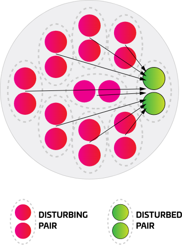
From a standards perspective, Alien Crosstalk measurements in the field are not straightforward. The realistic test configuration is to do a power sum computation of the alien cross talk noise from 24 pairs of 6 cables surrounding a pair in the cable under test, known as the 6-around-1 configuration.
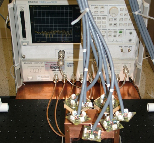
One of the main benefits of the GigaSPEED X10D solution is substantial reduction in alien crosstalk, enabling the potential channel capacity required for 10GBaseT. Using a 6-around-1 test configuration, the following test graphs for PSANEXT and PSAELFEXT show the excellent performance of the GigaSPEED X10D solutions.
Other forms of crosstalk are also present within the cable and connecting hardware themselves.

CTAT Spinning Pairs animation
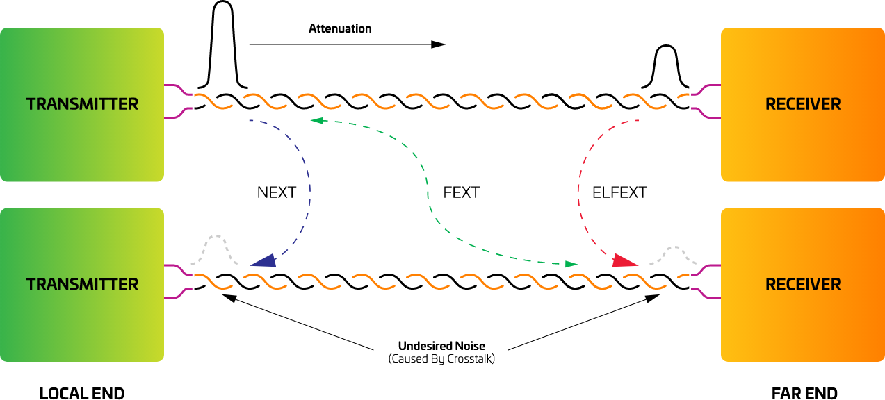
Near End Crosstalk (NEXT) refers to the undesired coupling of signals from the transmit pair onto the receive pair on the same (=near) end. NEXT isolation is expressed in dB and is a measure of how well the pairs in a cable are isolated from each other.
Pair-to-Pair NEXT
The pair-to-pair method is good for small pair-count cables (ie. 4-pair or less) and is the usual way of measuring NEXT. The measurement assumes one disturbing pair and determines the amount of signal coupled into other pairs in the cable.
Power Sum NEXT (PSNEXT) refers to the undesired coupling of signals from all other pairs into one pair. Basically Power Sum is a more stringent specification.
Far End Crosstalk (FEXT) refers to the undesired coupling of signals from the transmit pair onto the receive pair at the other (=far) end. FEXT isolation is also expressed in dB. For the newer high end applications this is now an important parameter.
Equal Level Far End Crosstalk (ELFEXT) is the same as FEXT, except that the coupled signal at the remote end is relative to the attenuated signal at the remote end on the pair the signal was applied to at the local end.
Power Sum Equal Level Far End Crosstalk (PSELFEXT) is the sum of the ELFEXT power from all other pairs in the cable. This measurement is applicable for parallel transmission schemes when more than two pairs is the cable are used to transmit in each direction (e.g. 1000BASE-T).
Historically, crosstalk was attributed primarily to cables, but as LAN speeds increased and the cables improved, other channel components started to contribute to the crosstalk. The cumulative effect became known as Composite Crosstalk, and the primary channel components that contribute to this are the cords, connecting hardware and cable. Crosstalk values can also be affected by the installation practices, especially the length of equipment, patch and work area cords and the amount of untwist of pairs within the cables. Connector crosstalk can be quite a problem, unless compensated for in the design of the connector. The crosstalk can also increase through any mismatches between the patch cords, connectors and horizontal cable. This is most noticeable on short links. Again if this is not accounted for in the design of all the components that make up the channel, a channel containing apparently standards compliant components may fail tests once installed.
Improving crosstalk cancellation in plugs and jacks
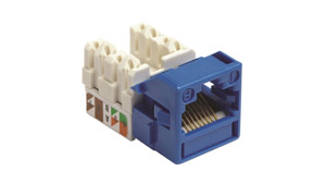
In order to achieve Category 6A performance when mating modular jacks and plugs, jacks need to be designed with crosstalk cancellation techniques to compensate for the crosstalk exhibited by the plug. So how can the performance of this “weak link” be improved?
The answer is found in the “perfect match” of backward compatible plugs and jacks. Overcoming the hurdles in the mating of plugs and jacks can lead to consistent performance for Category 6A connections. The first hurdle is in overcoming the variability in performance found in the plugs. As the key difficulty lies in the termination of cable pairs inside the plug, SYSTIMAX labs introduced in the GS10E GigaSPEED X10D plugs, a termination design that reduces variability to a negligible level. As soon as the cordage enters the plug from the rear, pairs are controlled and the untwisting of pairs and nesting of conductors required in conventional plugs is thus avoided. The second hurdle is in improving the mating performance of the jack. To take the performance of the jack to new levels while maintaining backward compatibility with existing plugs, SYSTIMAX Labs incorporated into its GigaSPEED X10D jacks additional crosstalk cancellation techniques unique in the industry.

Electric Field Modeling

Magnetic Field Modeling
The net result of the improved crosstalk performance in cable and connecting hardware is the optimum channel performance of an installed channel.
Demystifying frequencies beyond Cat 6A specs
On June 8, 2006, IEEE approved IEEE 802.3an-2006—specifying a new Physical Coding Sublayer interface and a new Physical Medium Attachment sublayer interface for 10 Gbps Ethernet. 10GBASE-T specifies a LAN interconnect for up to 100 meters of balanced twisted-pair structured cabling systems. Once specified, standards organizations such as TIA, EN and ISO/IEC confirmed component specs for Cat 6A cabling that supported 10GBASE-T applications. Each of these standardization bodies defines the maximum frequency for a Cat 6A component out to 500 MHz. Frequencies above 500 MHz were not defined since they would not be used, per IEEE specifications.
Some companies choose to advertise Cat 6A cabling with claims of performance out to 650 MHz or higher. However, though some cabling companies (including CommScope) routinely collect data out to frequencies beyond 500 MHz as a way of ensuring a stable manufacturing process, they do not promote performance beyond the 500 MHz maximum frequency for a Cat 6A component. CommScope disregards highlighting features it believes have no practical bearing on 10GBASE-T or Cat 6A performance and focuses on features it believes have a practical benefit to customers wanting to operate 10GBASE-T applications.
As LAN speeds continue to increase the transmission capability of a cabling system is reliant upon superior performance of not just the cable, but all the components in the LAN channel.
Manufacturers of end to end cabling systems (rather than manufacturers of individual components) have a significant advantage when it comes to end-to-end channel performance. It should be clear in this case that improved reliability and higher levels of performance is achieved by complimentary designs of cables, jacks and plugs. Similar considerations apply to the inter-relationship of other cabling system components, and only careful evaluation of the relative strengths and weaknesses of every component in the cabling channel allows for the necessary fine tuning.
The improvement in insertion loss and dramatic reduction in all types of crosstalk exhibited by the GigaSPEED X10D solution, exceeds the IEEE requirements for 10GBASE-T over UTP and the extrapolated TIA/EIA Category 6A and ISO Class EA channel performance specifications up to 500 MHz.
First offered to clients in 2004, SYSTIMAX GigaSPEED X10D is CommScope’s own implementation of Cat 6A - combining all the compatibility and functionality of Cat 6A with CommScope expertise and reliability.
- From the inventors of Cat 6A
- #1 Cat 6A vendor worldwide
- Consistent solution available in 150+ countries
- Manufacturing facilities around the globe
- Guaranteed Performance (Applications Assurance and 25 years Warranty)
- Supports HD, A/V, Wi-Fi 6 & 6E, PoE, IB cellular, IoT and much more
- Single network to support convergent applications
- Power and data on the same media
- Single-source end to end solution
- Ease of design, ease of deployment
- Proven reputation of reliability
- Performance beyond standards
- Supported by a global network of solution providers and CommScope’s engineers
- Supports IT & OT systems
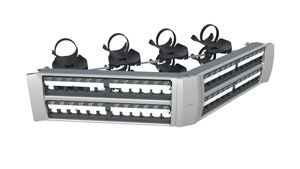
- Multiple footprints (panels)
- Preterminated option
- Automated Infrastructure Management option
Additional resource:
Structured cabling systems ordering guides
Download the ordering guide for your region:
SYSTIMAX: North America | Europe, Middle East & Africa | Asia Pacific | Caribbean & Latin America
NETCONNECT: Europe, Middle East & Africa | Asia Pacific | Caribbean & Latin America
Uniprise: North America
Cabling calculators
Cabling Pathways Calculator
This web tool provides an easy way to estimate how many cables would fit into a raceway or conduit, given a fill percentage. Users can select cable, trunks, raceways and conduits from predefined lists or define their own.
CommScope provides online training materials to help users develop a thorough understanding of both standards-based design using SYSTIMAX, and how it can be implemented in an ‘intelligent building’ context.
i Published in 2010, TIA-1179 recommends Category 6A for all new installations in healthcare facilities and was the first standard to recommend Category 6A for new installations outside of the data center. Similarly, published in 2014, TIA-4966 recommends Category 6A for new education facilities based on the need for high-performance infrastructure required for wired and wireless connectivity.
Why your Cat 6A has stood the test of time – and your mobile phone hasn’t
It’s 16 years old and still going strong. We find out what makes Cat 6A such an enduring technology.

