Multimode fiber: the Fact File
Introduction to optical fiber
When was optical fiber first conceived? Was it when Snell’s Law was formulated, leading to the concept of refractive indexes? Or when Bell invented the photophone? While these concepts helped advance fiber optics, many would point to Dr. Charles Kao’s pivotal research, presented in 1966 to the Institute of Electrical Engineers, as the defining moment in fiber optics—for which Dr. Kao was awarded a well-deserved Nobel Prize.
Along with advances in optoelectronics, fiber technology has quietly enabled much of what we take for granted today, such as the internet, high-speed video and even mobile networks—all of which rely heavily on fiber backbones to ensure high quality of service. Fiber technology enables significantly lower cost, higher capacity bandwidth at much greater distances than other media such as coaxial, microwave and satellite.
We at CommScope are very proud of the role we have played in bringing fiber optics to the telecommunications network: whether providing next-generation wideband multimode fiber in data centers, high-density optical distribution frames for fiber to the home, or fiber-to-the-antenna solutions, we continue to generate innovative solutions for our customers that are based on optical fiber technology. We’ve made it much easier to connect to the fiber superhighway.

Understand the speed advantage of OM5 Fiber

Understand the speed advantage of OM5 Fiber

Understand the speed advantage of OM5 Fiber
Would you like to read offline?
Download a PDF version of this article to read again later.
Stay informed!
Subscribe to The Enterprise Source and get updates when new articles are posted.
All optical fiber cables are constructed with a basic design composed of at least two optically different materials.
Both fiber types, singlemode and multimode, are optical wave guides. The light signal is contained within the “glass” core by the cladding, which is very much the same crystalline structure but doped differently (Boron, germanium in variable percentage, for example).
Core: center optical layer of the fiber where the light is transmitted.
Cladding: outside optical layer that traps the light in the core and guides it along.
Buffer coating: hard plastic coating that protects the glass from moisture or physical damage.
Optical fibers are based on the principle of total internal reflection: The light that travels inside the fiber core is reflected back into a core when it reaches the boundary between a cladding and a core.
The light signals propagate through the core of the optical fiber, but the way they propagate differs depending on the fiber type.
The fiber type name is self-explanatory; the propagation path is single (singlemode fiber) or multiple (multimode fiber).
Note: The reality is that singlemode fiber actually transports eight to 10 modes, which, in order of magnitude, is considered “single” compared to the 1,300 modes a multimode fiber can transport. The mode in which light travels depends on:
- Geometry
- The index profile of the fiber
- The wavelength of the light
The geometry factor is heavily dependent on the size of the core:
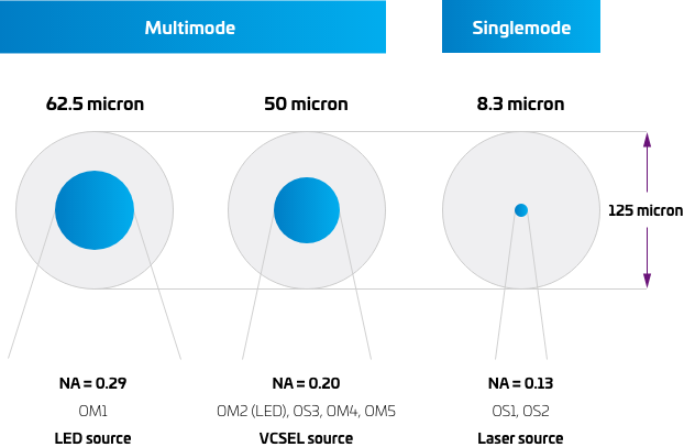
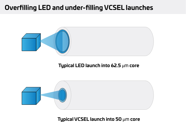
This graphic should help you visualize the physical differences between the fiber types. All have 125-micron outer diameters (the cladding dimension). They differ in the size and construction of their cores. The larger diameter core of 62.5 and its larger numerical aperture (NA) make it the best choice for LED-based systems, because it gathers more light from the larger emission pattern of typical LEDs. A 50-micron size is less efficient for LEDs, but the narrower emission pattern of VCSELs (laser diode) couples equally well into both 50 and 62.5 micron. The lower light gathering ability of 50 micron means it carries fewer modes and, as a result, has higher bandwidth overall than 62.5. This is taken to the extreme with singlemode fiber.
When should we choose one type over the other? This depends, as always, on your requirements.
SINGLEMODE
MULTIMODE


- If you need long transmission distances (up to 40 kilometers in enterprise environments, excluding the long-haul systems) you’d go for singlemode systems.
- If you don’t need to support long distances—let’s say you don’t need any link longer than 550 m, and want to limit the total system cost (including active equipment)—you’d probably choose multimode fiber.
- Multimode fiber supports high data rate applications (same speeds as singlemode but shorter reach).
- Multimode fiber systems are easier than singlemode to maintain and keep clean. Contamination (for example, dust) at the connector interfaces is a headache for any fiber system operator, but the multimode fiber system’s connector interfaces are less susceptible to dust than are singlemode systems. Copper interfaces, on the other hand, typically are not susceptible to such contamination.
Distance
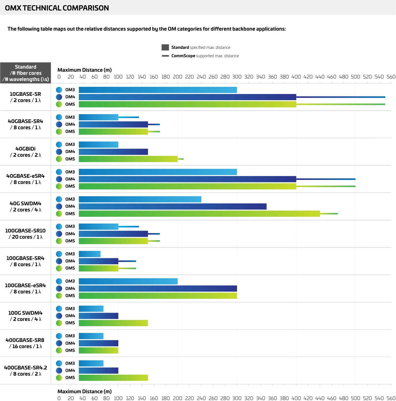
Depending on the intended application, supported distances range up to 440 m (though CommScope’s solutions can reach up to 550 m; see the “OM technical comparison” section). The distance and connections in a link need to be considered, and design tools can help with this selection.
Maintenance
Given the bigger core diameter and the higher alignment tolerances, compared to singlemode, it is inherently easier to maintain multimode fiber and to keep the connector interfaces clean.
Cost
Link costs include the cabling components and the transceivers. In its sweet spot multimode fiber and multimode transceivers combine to potentially provide an attractive low-cost option. When distance exceeds the capability of multimode fiber, then singlemode systems take over.
The standards
OM3 is usually considered to be the bare minimum choice nowadays. As new higher-speed applications emerge, the limitations of OM3 begin to show—potentially forcing shorter reach that doesn’t support the scale data centers may require. For many, it is not a long-term play.
Everyday choice
OM4 is a commonly chosen standard today. It provides a higher bandwidth (capacity) than OM3, so OM4 is the typical recommendation for new applications.
Multiple wavelengths
The industry now has the ability to use multiple wavelengths over MMF (SWDM) similar to WDM on SMF. This is a key boost to the capacity of MMF. Here, multiple wavelengths combine to increase the capacity 4X (SWDM4 protocols). CommScope led the introduction of OM5, designed to complement SWDM, providing higher bandwidth—which translates to longer reach for more wavelengths. OM5 is now the future ready standard.
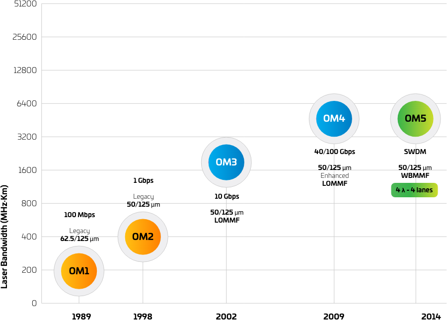
- Multimode fiber (MMF) first deployed in telecoms networks.
- MMF first used in public networks and in enterprise networks, supporting applications such as private telephone switches (PBXs), data multiplexers, and LANs.
- Ethernet and fiber applications grow. Multimode fiber becomes the main media for backbone and other deployments that require reach beyond the capability of copper twisted-pair cabling.
- Data rates surpass 100 Mbps—850 nm VCSEL becomes more cost viable than LED sources.
- This sparks a conversion of MMF core diameter from 62.5 µm (OM1 cabling) to 50 µm (OM2 cabling).
- The gigabit era dawns and limitations with the bandwidth measurement techniques become clear.
- Bandwidth characterization via a newly standardized differential mode delay (DMD) measurement advances. This employs many different laser launches to extract a minimum laser bandwidth.
- Fiber passing the new measurement became known as laser-optimized multimode fiber (LOMMF).
- The first LOMMF offers a bandwidth of at least 2000 MHz*km at 850 nm—known as OM3
- OM3 gains significant market share.
- OM4 arrives, offering at least 4700 MHz*km in anticipation of 25 Gbps per lane applications.
- OM3 and OM4 are the primary fiber media for Ethernet and Fibre Channel applications.
- Parallel MMF applications are standardized within Ethernet and Fibre Channel at rates at least 40 Gbps using at least four pairs of fibers.
- 40G BiDi and SWDM4 emerge using multiple wavelengths on MMF (850–950 nm) increasing the bandwidth of MMF and replacing some parallel applications.
- WBMMF (wideband multimode fiber) is standardized to extend the capability of VCSEL-based SWDM transceivers.
- 40G-SWDM4 and 100G-SWDM4 transceivers are defined by multisource agreements backed by the SWDM Alliance.
- WBMMF becomes recognized as OM5 in structured cabling standards globally.
- OM5 is a recognized media in emerging Ethernet and Fibre Channel standards at rates of 50G, 64G, 100G, 200G, 400G, and 800G.
- The IEEE introduces the first multiwavelength MMF application 802.3 cm for 400G up to 150 m.
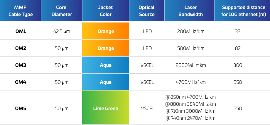
Over the course of natural technological evolution, five different fiber classes have been developed. As we’ve seen in the history section, the first multimode fiber had a 62.5-micron core (OM1). It was used for many years, along with the more capable 50-micron version (OM2). Those two types are now rarely used.
The OMx nomenclature comes from the ISO 11801 standard and ranges from OM1 to OM5. We will now describe each and compare their construction and supported distances and applications.
OM1
Designed originally for all multimode applications using LED transmitters, OM1 is based on a 62.5-micron core. Indoor cables are identifiable by the traditional orange color jacket. OM1 just supports 10G up to 33 m (10GBASE-SR). In the context of enterprises today, many consider OM1 usable just for expansions or repairs of old installations that require low-bandwidth applications.
OM2
Quite similar to OM1, but with a 50-micron core. Supports 10G up to 82 m given its slightly higher bandwidth.
OM3
First of the laser-optimized fiber types.
In the mid-90s the VCSEL-powered light sources were introduced, which caused a market shift to 50-micron optical fiber. The laser-optimized multimode fibers (LOMMF) provide higher bandwidth and enable higher data rates in short-reach applications. The total system cost (including electronics) remained low compared to singlemode systems.
To make the bandwidth capacity visually clear, the aqua color jacket was normalized.
CommScope patented the specifications for this type of fiber (albeit the OM3 name comes from the ISO 11801 standard) and was the first manufacturer to launch a commercial solution (LazrSPEED® 300). OM3 supports 10G up to 300 m.
OM4
As an evolution of the OM3 specifications, the 50-micron OM4 fiber type has gained substantial popularity. OM4—with more than double the effective bandwidth at 850 nm—introduced extended reach for existing applications (gigabit and multigigabit applications) and enabled future applications. It’s worth noting that CommScope’s LazrSPEED 550 was the precursor to this standard.
Backwards compatible with OM3, it supports 10G up to 550 m. The jacket color is also aqua. See the supported distances chart in the next section to get specs for other applications.
OM5
Also called “wideband multimode fiber,” or WBMMF, it’s another of CommScope’s breakthroughs. OM5 supports a technique named short-wavelength division multiplexing (SWDM) that enables the use of four different lanes (at four close wavelengths). Hence it needs four times fewer fibers for the same capacity. OM5 retains the legacy application support of OM4.
To distinguish it from previous types, the OM5 jacket color is lime green. (Why lime green? Because singlemode is yellow and OM4 is aqua. If you combine the best of both, you get lime green.)
There are unofficial fiber names, such as OM4+, marketed as an alternative to OM5, or superior to OM4. You can find out more about the differences in this white paper.
To learn more about the history of MMF and better understand the implications of the OM5 innovation, check out this white paper.
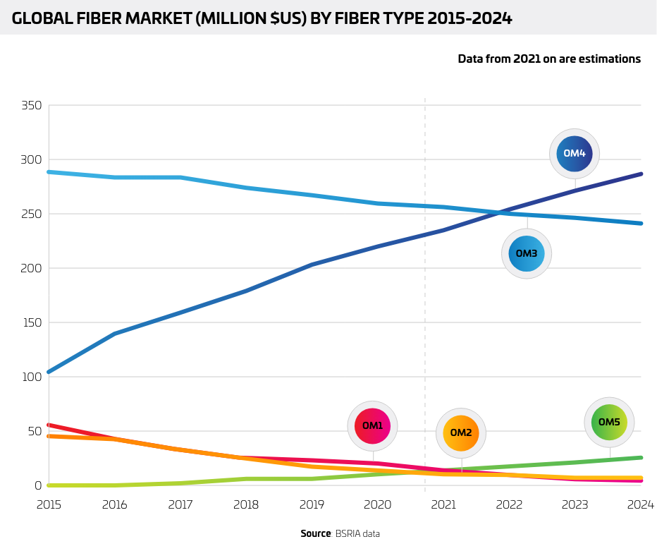
Market evolution
How has the market reacted to the tech evolution? See the chart below. Admittedly, the more capable the fiber type, the higher the price—so that plays a role in the market.
For tips you may find useful when designing your network, you can consult this design guide.
DMD (differential mode delay) describes the difference in delay time between the latest and earliest arriving pulses in multimode fiber. This “pulse spreading” limits bandwidth and is the main reason conventional OM1/OM2 multimode fiber cannot properly support 10 Gbps.
In multimode fiber the dispersion is caused by modal and chromatic dispersion. Modal dispersion exists because the different light rays (modes) have a different path length; therefore, rays entering at the same time will not leave the other end of the fiber at the same time. The modal bandwidth is controlled by the pulse broadening due to the differences in many propagating modes (300 to 900).
The modern multimode fibers have a structure that reduces the effect of the modal dispersion. These fibers, called “graded index fibers,” are used in all SYSTIMAX® SCS multimode fiber products.
With multimode fiber transmission, distances of up to 2 km are possible; however, as speeds increase, the distance support is reduced. Adding connectors (which reduce the signal power) also limits the distance that applications can support. Higher bandwidth and better connectivity provide optimum performance from MMF systems.

Differential mode delay (DMD) testing method
For singlemode systems, the glass core diameter has been reduced to a size where only one path (mode) can propagate through the fiber. The modal dispersion is no longer present. However, dispersion still exists in a singlemode fiber. Different wavelengths travel at different speeds in glass. These wavelength differences give rise to “chromatic dispersion.” Chromatic dispersion is related to the light source, which normally has a range of wavelengths.
SC and FC connectors were once the kings of the fiber connectivity realm, but have been unable to keep up with increasing requirements for density, performance, scalability, and ease of deployment.
The industry instead adopted LC and MPO connectors and has used them for some time—and for very good reasons. Get a clearer perspective of the advantages of LC and MPO connectors in the video below. Connectors will be covered in more detail as a separate main topic on this page.

Overview of fiber connectors
On top of what you have read in the previous sections, we need to have a look into what the future may bring. Some data centers are looking to make the jump to 400G. A key consideration is which optical technology is best. The optical market for 400G is being driven by cost and performance as OEMs try to dial in to the data centers’ sweet spot. You can find more information here.
One other aspect to consider is the number of fiber cores that will be needed in the future to support high-demand applications. Even using the multiplexing capability of OM5, some applications like 400G or 800G will demand multiple fiber cores per link—and a DC has a huge number of links. So higher fiber counts may become a must in DCs. Learn more about this in our expert’s article.
The need for data and power across fiber
Network devices are popping up everywhere in buildings and across campuses—devices like small cell sites, Wi-Fi access points, IP cameras, building access and inventory controls, and countless others.
While these new applications improve user connectivity, operational technology efficiency and property-wide safety and security, they also present you with a new and growing challenge: getting high-bandwidth data and power connectivity to every device in every location, indoors and out, with the low-latency performance needed to leverage edge network architecture.
A powered fiber solution makes it relatively easy to meet those challenges in a single, easy-to-handle cable run, with options suited to weatherized outdoor deployments or plenum-rated indoor installations.
A powered fiber solution combines high-performance, low-latency fiber-optic data connectivity with a copper low-voltage dc power connection. This helps enable the connection of many powered remote devices without the need for new conduit, bulky extra cable runs or expensive electricians. With the powered fiber cable solution, your network can gain access to a vast and growing ecosystem of network-connected applications, including:
- Optical LAN
- Emergency phones
- HD security cameras
- Digital signage
- Wi-Fi access points
- Small cells
- Or virtually any low-voltage dc-powered device
The performance of CommScope’s fiber systems is guaranteed and backed by our Application Assurance.
CommScope has a history of being a leading innovator, developing OM3, OM4 and OM5.
CommScope Solutions (LazrSPEED variants) were released years ahead of the publication of the applicable standards, allowing our customers to surf the coming wave ahead of the trends.
End-to-end complete solutions: cables, panels, patch cords, connectors, etc.
Broad portfolio to choose the best elements for your needs.
Fiber connectivity with AIM option (automated infrastructure management) with imVision®.
Preterminated options to help meet data centers’ agility requirements.
Added network flexibility by supporting more connections in the fiber links and extended distances compared to standard applications specification with ultra-low-loss (ULL) components.
As a medium for transmitting data, fiber is more powerful than copper. However, installation is more complex as a result, and skilled expertise is required. CommScope’s PartnerPRO® Network may be a useful tool on your path toward certification and expertise.
If you or your team are looking to learn more formally about multimode fiber, we have two courses that enable students to learn at their own pace. Both are available online in multiple languages.
Multimode fiber vs singlemode fiber vs copper: a battle you can’t lose
Why there may never be a winner or loser—and why that’s a good thing.


